
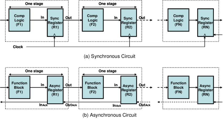
Overview of the Organization of Logic Pipelines in Async. and Sync. Digital Circuits [8]
An asynchronous circuit is a sequential digital logic circuit that does not use a global clock circuit or signal generator to synchronize its components. Instead, the components are driven by a handshaking circuit, which indicates the completion of a set of operations. [1, 2] Due to the elimination of a global clock, asynchronous circuits have the following advantages: [2]
However, as is evident by the market share, Asynchronous circuits saw very limited use in practical chip designs. Here are some possible explanations:
To summarize, asynchronous circuit design is and probably will never be mainstream. However, I personally believe that understanding async techniques and using them strategically in certain building blocks in circuit design can yield a truly optimal system design.
Another note on the higher speed implication: I believe async circuits may still be relevant in trailing-edge CMOS technologies and non-CMOS processes such as thin-film-transistor technologies [7]. Because in those technologies, the logic speed is still heavily bottlenecked by the slow transistors; getting higher clock frequency is still desirable for the industry.
A circuit that operates "correctly" with positive, bounded but unknown delays in wires as well as in gates is classified as delay-insensitive (DI). However, barely any useful circuits can be derived under this restriction. A more useful type of circuit called “Quasi-Delay-Insensitve” (QDI) relaxes the restriction a bit by allowing isochoric forks. [2]
The following is a diagram showing such a fork structure and the criteria it needs to meet to be qualified as QDI. It’s also possible to further relax the restriction to create new circuit families like “Scalable-Delay-Insensitive” (SDI) [9], but it is out of the scope of this writing.
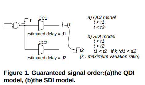
Isochronic Requirements of QDI and SDI Circuits [9]
People tend to associate asynchronous circuit design with “pipeline” type structures. This is evident based on the fact that most instructional materials [12] tend to illustrate asynchronous circuits using examples as shown below:
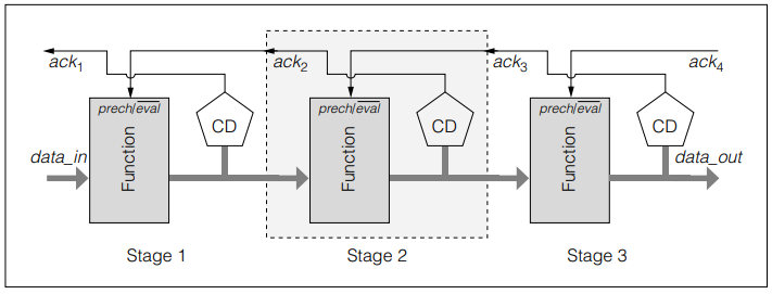
"PS0-Style" Dynamic Pipeline [12, 13]
However, it turns out that this is a very early and primitive way of describing async data flow. There is a strong disconnect between this kind of dataflow and practical ones like the register file in the AMULET 1 microprocessor:
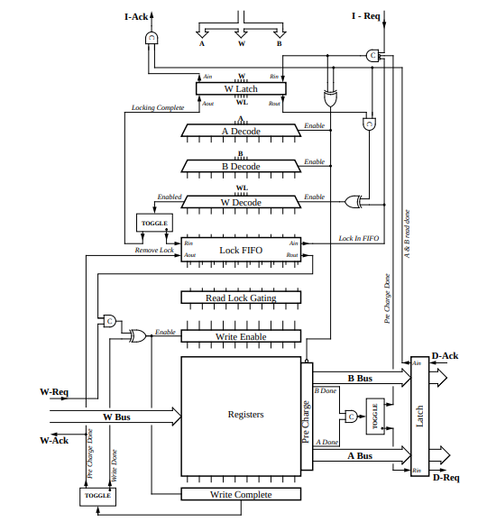
Organization of the Asynchronous Register File in AMULET1, Representing a More Practical Case [14]
It turns out that it’s possible to implement complex function blocks will only a couple of gates. To achieve this, a different technique needs to be employed.
In more recent publications, Petri Net (PN) or Signal Transition Graphs (STG) are the most common and more practical ways to describe more practical and complex asynchronous control structures. To illustrate this, I present a simple controller that takes data from external memory, performs some operations on it, and writes it back. When devising this circuit, the circuit designer has to take into account that it’s undetermined whether the data calculation will finish first, or the address calculation will finish first.
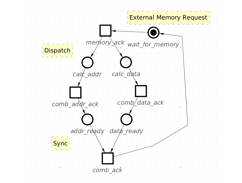
Example: A PN of Simple Async Memory Operations
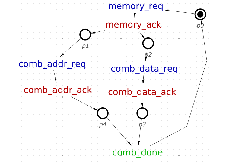
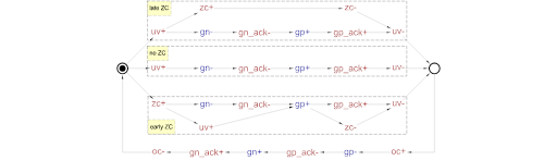
The same Diagram is Represented in STG. The Ack & Req Signals are Explicitly Labeled
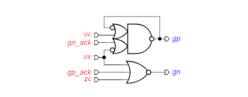
By the end of the 1990s, a number of mathematical techniques had been developed to synthesize PN and STG dataflow models into QDI circuits; methods of abstraction, analysis, formal verification, and circuit synthesis had already been established. [10, 11] With the help of those tools, I was able to get this result:
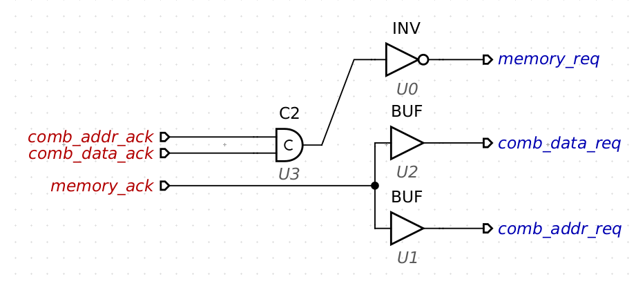
The Control Circuit Represented by the STG Graph Is Converted into Technology-Mapped Circuit Elements using MPSat.
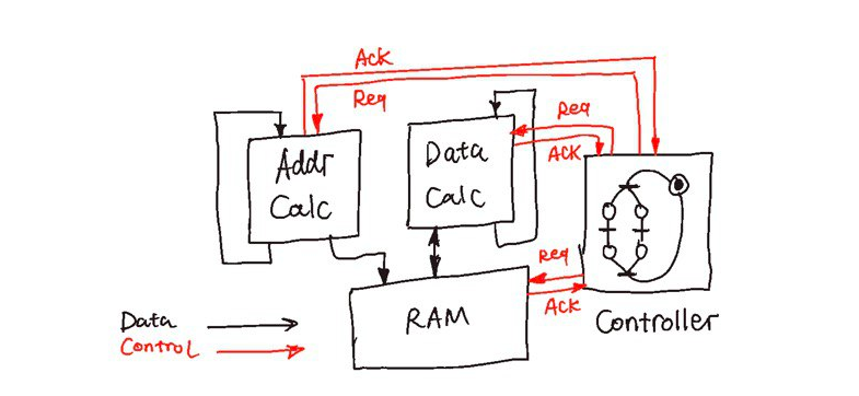
An Illustration of the Position of Controller and Functional Units in a General Asynchronous System
The Muller C-element is a latch that synchronizes the phases of its inputs. A symbol for a 2-input C-element and its timing diagram are shown in the figures below. Initially, all the signals are in the low state. When both inputs in1 and in2 go high, the output out also switches to logical 1. It stays in this state until both inputs go low, at which stage the output switches to logical 0. [1, 2]
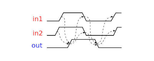
Timing and edge relation diagram of a C-Element
In the original publication, when constructing the ILLIAC II computer, Dr. Muller described the element as a “Cumulative State” (C-State) holder.[3] From a modern perspective, the C-element represents a node at which the branched events join. So, it’s also referred to as “rendezvous ” or “join” operations in some publications. [4] This element made larger, delay-insensitive asynchronous circuits possible because non-ideal timing jitter and skew can now be compensated at a gate level to ensure isochoricness.
In QDI implementations, it’s very common to find C-elements in synthesized circuits. Sometimes, it can be implicit. For example, the following circuit is a “complex-gate” implementation of a buck DC-DC controller from the Workcraft examples:
STG of a 3-state Buck Timing Controller [5]
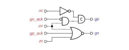
“Complex Gate” Implementation of the STG, Generated using the MPSat Backend
Note that this circuit actually contains an implicit C-element, because the complex gate at the top has a feedback loop. The same circuit can be broken down into “standard-C” implementation, as shown below. [6] In this version, the C-Element is made explicit.
“Standard-C” Implementation of the same STG, Generated using the MPSat Backend
In its essence, Muller-C is a special case of latch circuit and can be broken down into smaller elements. To ensure correct operation, the circuit must be able to traverse in the state space (i.e. the Karnaugh Map) without generating any glitches during the transition. This requirement makes it a bit tricky to implement with sub-gates: very often, special constructs and additional gates need to be added to ensure glitch-free operation.
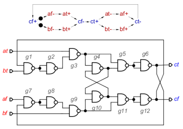
A Dual-Rail C-Elemented Constructed using only Nand Gates, [7]
For this project, I decided to implement the Muller-C element in a more traditional transistor-level approach. The layout is drawn in MAGIC VLSI in the GF180 open-source PDK.
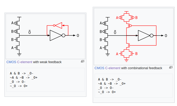
Two Popular Gate-Level Implementations [8, 9]
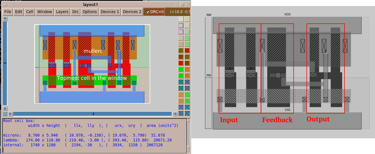
Implementation of the circuit in GF180 9-Track StdCell Format
On the critical path that dictates the throughput of the system. It’s very common to find function units whose evaluation time is strongly data-dependent. It’s historically known that the biggest advantage of asynchronous circuit design comes from self-clocking based on completion detection: Instead of waiting for the slowest possible scenario of a combinational block, the clock edge is delivered at the monument the computation is done, yielding the fastest timing possible.
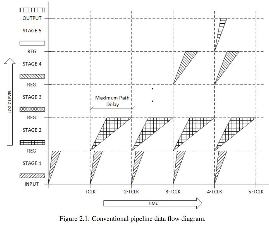
Illustration of a Problem with Conventional Pipelines: The Clock Period is Dictated by the Slowest case of the Slowest stage. [4]
The discussion is based on “completion detection”, which seems to indicate some special kind of logic, such as dual-rail logic that naturally indicates where the evaluation is done [5], or uses the current flow waveform to determine if the evaluation is done [3]. To make implementation easier, there are two less-than-ideal but general methods that can be applied to any combinational block: fixed delay, and steady detection. [6]
This technique has been demonstrated in an asynchronous FPGA project [1], where most non-critical combinational operations are implemented using fixed delay.
Note that the possibilities of acquiring the completion signal are infinite and often need to be custom-made case-by-case. It’s also not restricted to the scope of combinational logic circuits. For example, a very common example is the controller of a SAR ADC. With the goal of checking if the clocked comparator in the loop has done comparing the input, the completion detector needs to figure out if the two outputs have diverged. [7] Other examples include asynchronous SRAM and DRAMs. [8]
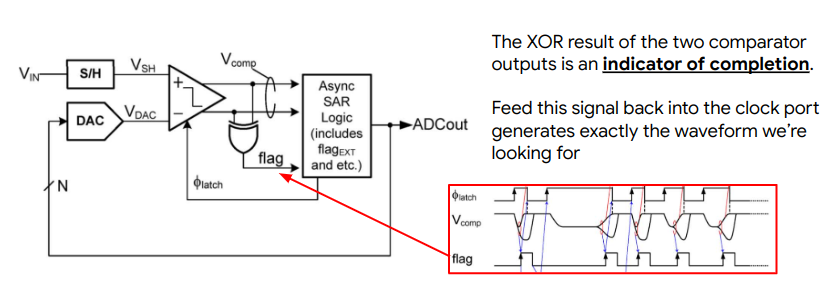
Completion Detection Problem in SAR ADCs [7]
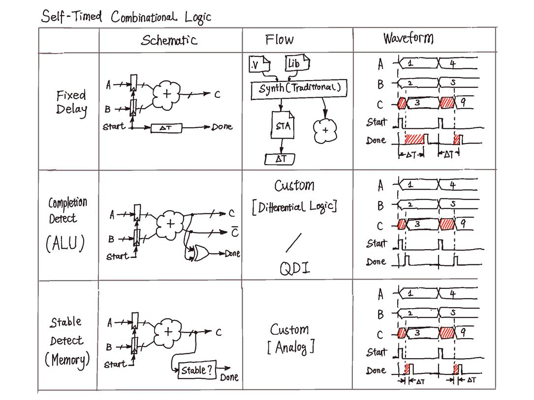
An Illustration of Different Ways to Generate the Completion Signal