
 (Content Recycled from Lithcore.cn/3583)
I received this 9100B in Sep. 2021. It came in very good cosmetic condition, but didn’t do anything when plugged in: Not even the indicator lights. With the help of the internet, I’ve successfully identified a few problems in the power supply. I have also found some core-memory circuit malfunctioning that haven’t been encountered before. As a return, I’m now writing this post to share my diagnosis process and some over-saturated photos.
Before I start, I shall provide all the materials I used during my diagnosis process:
Thanks USPS, my machine came in one piece. I visually inspected each board and tube in this machine. I can’t find obvious burn marks or blown transistors, nor any blown fuse, which is a good sign.
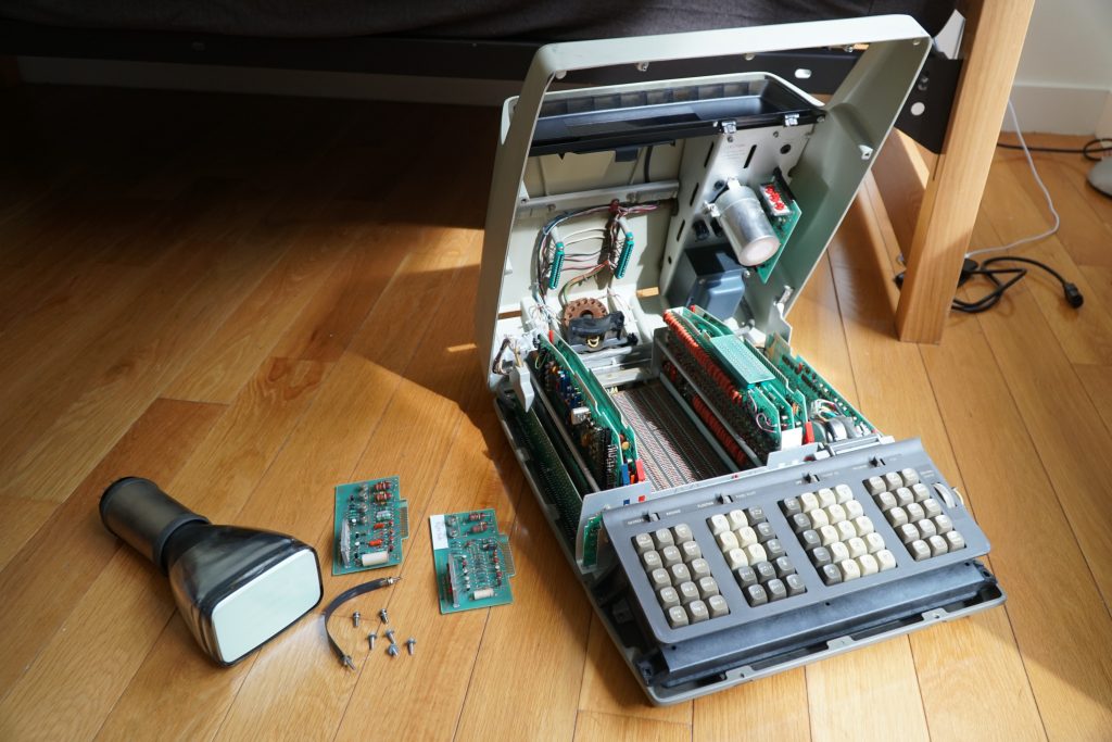
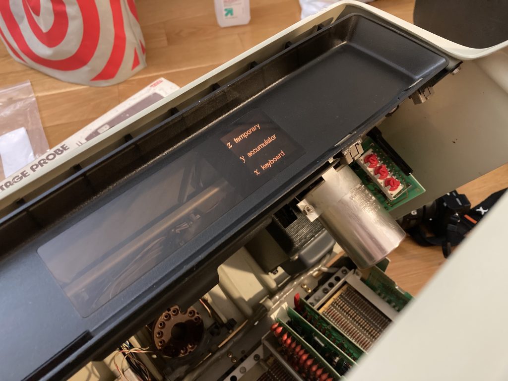
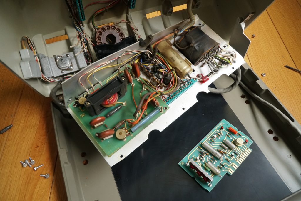
The machine with its display portion removed
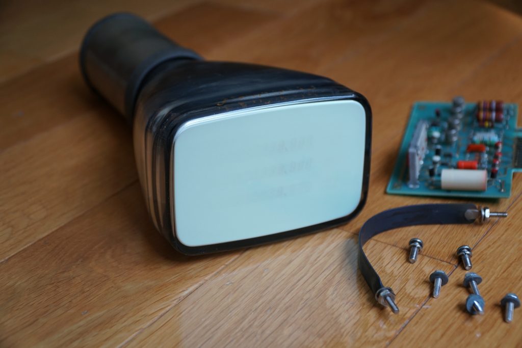
The CRT with some shrinken burn marks
I saw burn marks concentrated near the center portion of the display tube. According to BD4SUP [5], this is likely to be caused by a failing HV supply putting out too much acceleration voltage. I suspect the HV supply in my unit is also dead.
No known replacement is known for this specially designed display tube. If it is broken, the chance of finding a replacement is virtually zero.
Since all other rails are generated by the linear-regulated -15V supply, nothing happens when I switch the machine on.
Thanks to the friendly design of this machine, all -15V loads can be removed by undoing only one plug & removing the HV fuse. After removing all the load, still, no -15V. HP Service Manual instructed me to check the largest regulating transistor (A20-Q1) mounted mechanically on the chassis. It seems to be fine.
The -15V regulator feedback circuit operates on another coarsely regulated +34.8V DC power rail. The -15V voltage comes from a floating transformer secondary + diode bridge, which creates a constant 24V DC voltage across its outputs. By rising the opposite output above ground, the -15V is regulated. That’s why the entire feedback circuit operates on a positive voltage.
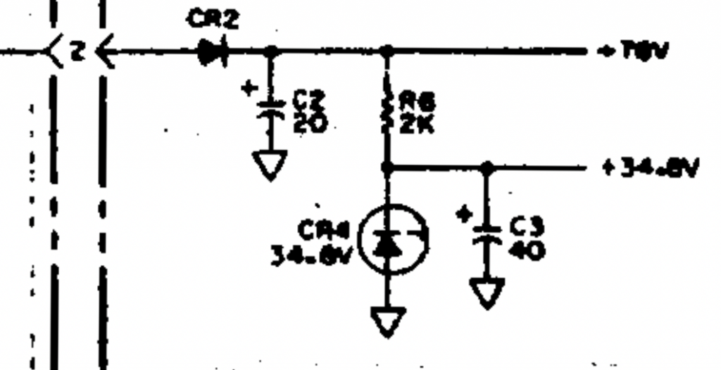
Board A21, +34.8V Supply, <2< is an AC transformer winding
In my case, the +34.8V is directly shorted to the ground. A dead-short axial capacitor! Thank god the failed capacitor is not A21-C2. Otherwise, a blown transformer winding will be a repair nightmare.
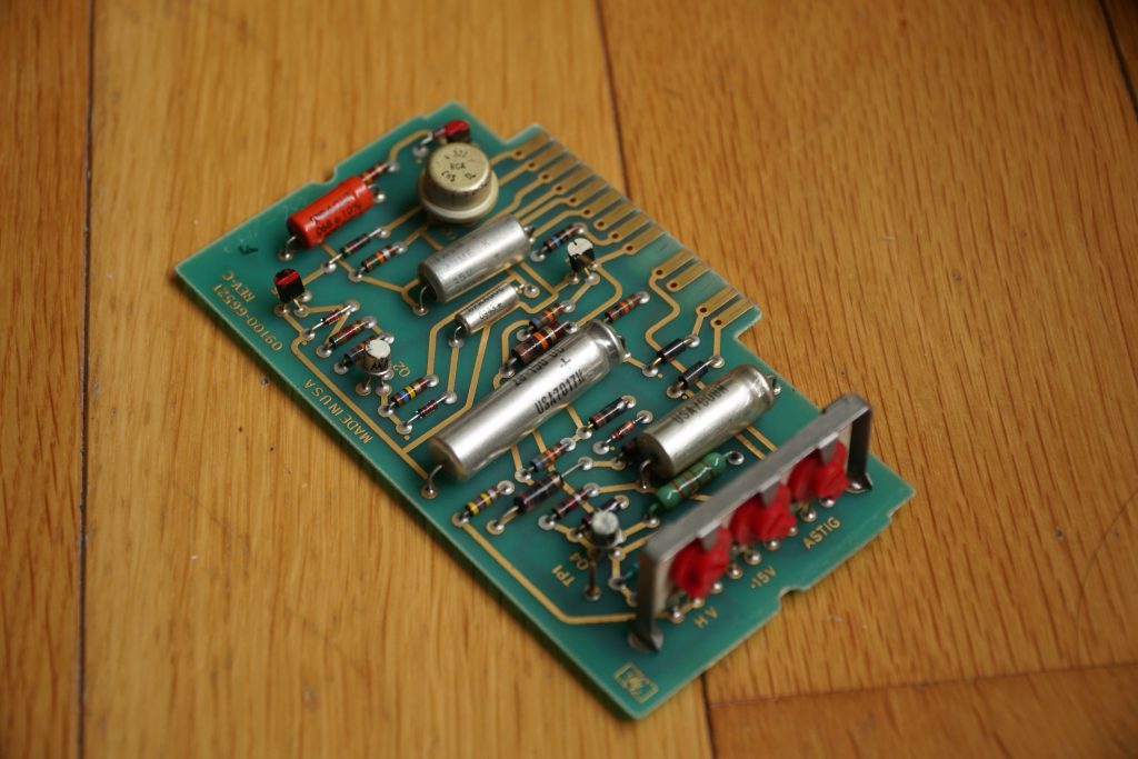
Faulty LV Supply / Feedback Board
By taking out A21-C3, -15V is recovered. Sooner or later I will replace all axial capacitors on those boards.
With New Bulbs Installed
In my case, the register indicators still won’t turn on. But these bulbs are connected directly to -15V, which means they are just blown at some point during their years of service – a very common failure. The previous owner didn’t bother to change them when the calculator was still working.
The Computation Error Lamp – Is anyone saying “HPE”?
HV power supply failure is another very common issue. The voltage spikes generated from the primitive self-oscillating DC-DC circuit can quickly wear out the switching element and the regulating diode. Replacing those two elements should fix those issues. [1][2]
BD4SUP recommended TIP41 as the self-oscillating element replacement. It is apparently a much more reasonable choice compared to most other suggestion you can find online. This kind of oscillator relies on the ICSat parameter to operate. HP had a preference for hand-picking the oscillating element to nail the device parameters.
The HV Section
In my case, the transistor seems to be healthy, but that 10kV diode has certainly died. HV circuits are always scary to repair. I have to wear gloves to prevent leaving fingerprints on the board – skin oil is conductive at this voltage. Arching of the switching HV can burn a hole through the board! HP had also kindly reminded that the conformal coating must be left intact.
If something catastrophic happens, I will replace the design with a modern one instead. But thankfully that didn’t happen.
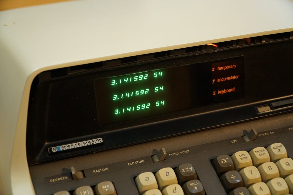
Oh...Our cute little pi is not feeling well
This problem is a tricky one. I remember seeing folks on the HPMuseum forum mentioned a similar issue. But no answer is given in those threads.
Number mostly works, addition and subtraction work, but there’s always one digit missing on the display, and almost any function other than addition/subtraction/multiplication causes a halt, where the machine becomes completely non-responsive, and the display is blanked.
I suspected there might be something wrong in the ROM, there might be an unaddressable page or something – I thought.
The famous PCB ROM is beneath the huge gold plating. BD4SUP have seen too many broken diodes and resistors on this kind of boards before
Later, I saw a memory map in the schematic[3].
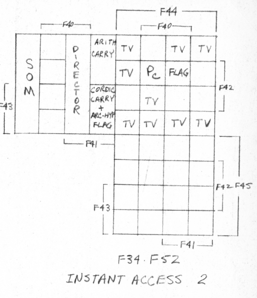
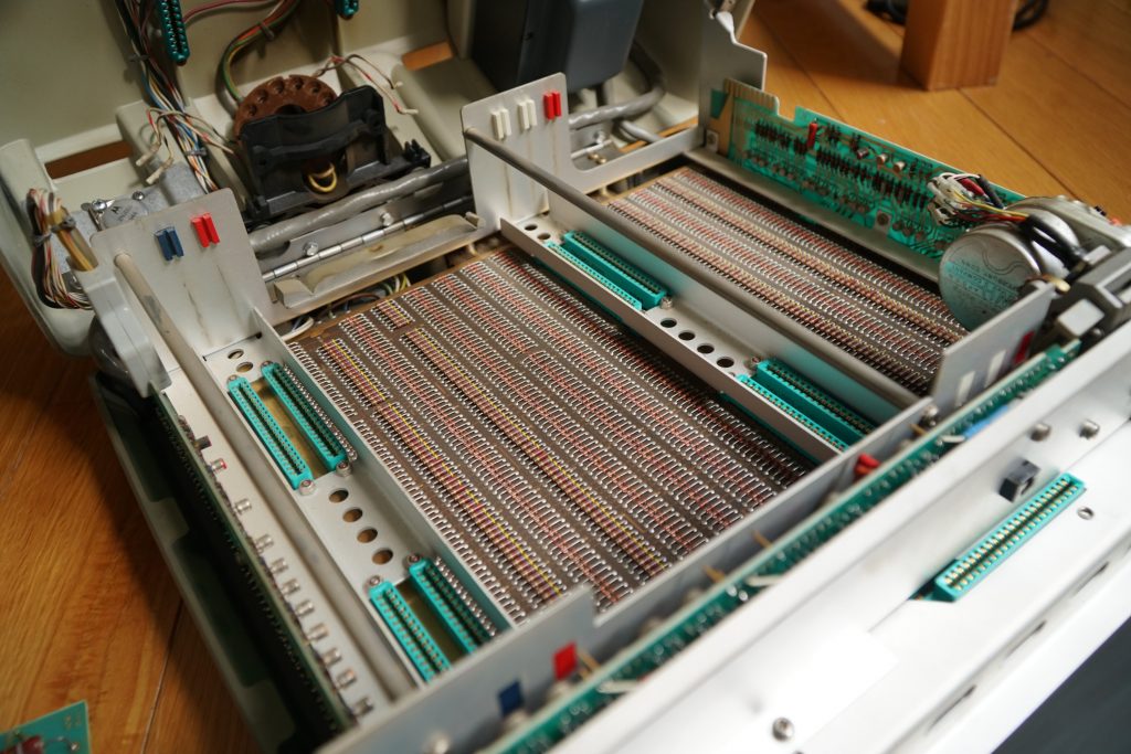
The Core-Memory Map, Part 3/3
What happens to the CORDIC/SQRT/Division routines, if one digit in the memory is broken? I learned this from the fantastic articles written by Jacques Laporte on the HP-35 math routines. These early machines do math in the serial-BCD faction. If one digit in a long BCD number refuses to change/stuck to strange values, those serial operations can get into an infinite loop, thus halted.
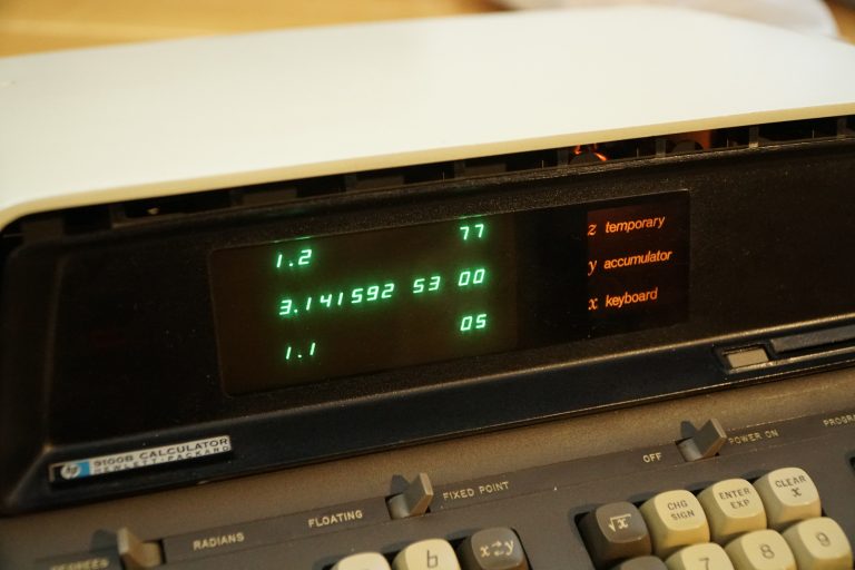
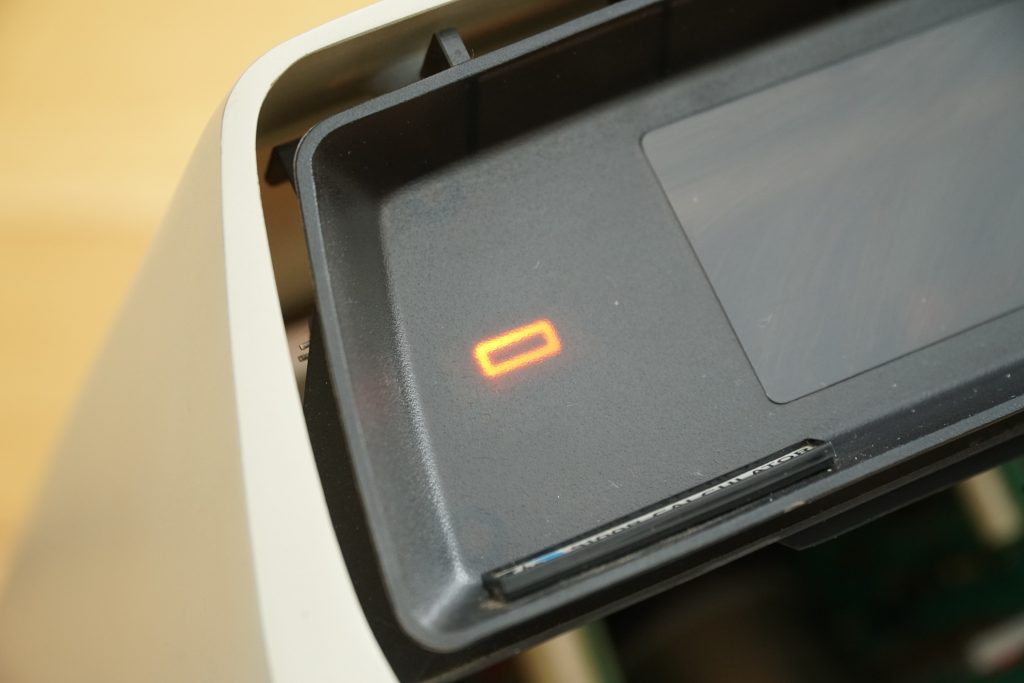
Octal 77 confirms the issue
Luckily the memory failure didn’t affect the program editing functionality very much. I can still write data into the two pages in the program mode. I found that any address on the +page ending with “2”, that is, the “D2” digit, is permanently stuck to 77 (6’b111111 in octal).

“char” (i.e. BCD Digit) & Page & Transistor Annotation

Magnetic Core Memory Circuit Schematic
The schematic says that transistor Q79 on the core-memory board is responsible for this particular digit – either the transistor is open, or its supporting circuits are gone. There’s no silkscreen indicating which transistor is Q79. By tracing from the wiring map on page 1, I was able to find Q79 by tracing from the test connector.
Poor Q79 is pronounced dead
The part number of this PNP transistor is a mystery: On the cans it writes “3-093”, which is a common “HP abbreviation” for 1853-0093. Unfortunately other than it being listed in an HP catalog (no further info provided other than the $1 price tag), I can find no info about this transistor anywhere. Some suggested that it might be an early VHF-grade transistor, capable of operating at high frquency (The clock frequency of this machine is ~1.19MHz, the fT must be much higher than this) with high gain.
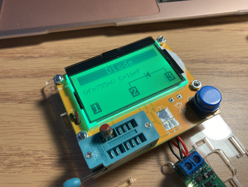
I desoldered an adjacent transistor, the DC gain of which is around 160. So I ordered a pack of 2N4403 (hand-picked hfe=160, fT=200MHz). They turned out to be working great.
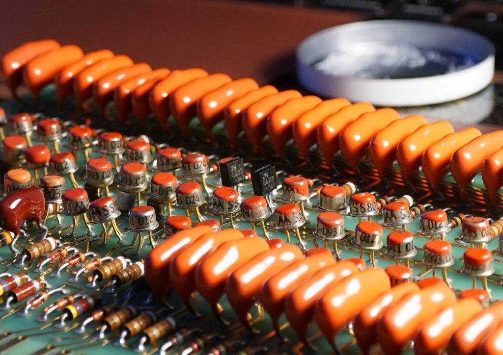
(Warning! Those transistors shown are not Q79, I’ve replaced and swapped some of them just for testing)
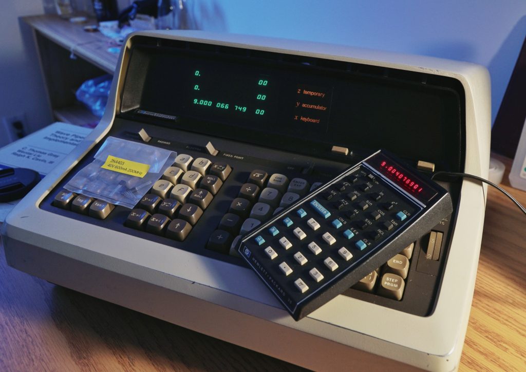
Alas!
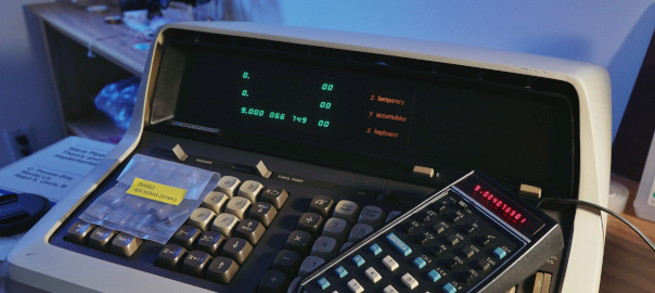
Now this machine passes the self-test, it’s fully functional again! Check out the outdated asin(acos(atan(tan(cos(sin(9.0)))))) result!
Actually, thanks to the high clock frequency and enormous ROM, the performance of 9100 is much, much better than that of the HP35.
(Known as the Forensics Test: http://www.rskey.org/~mwsebastian/miscprj/results.htm)
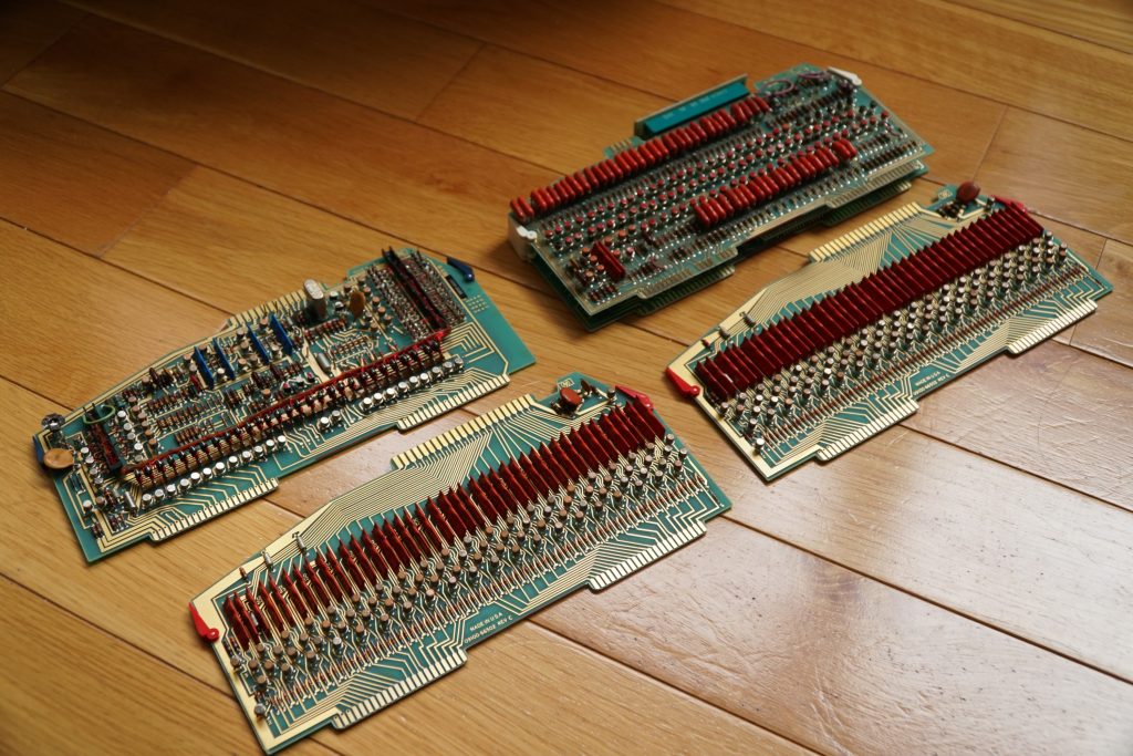
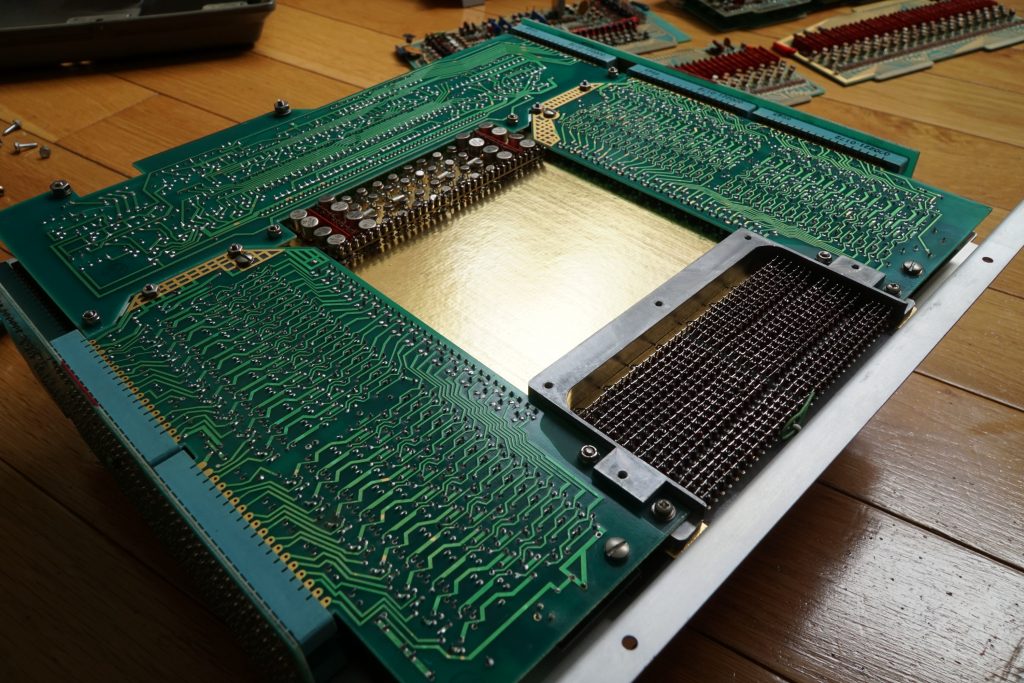
Logic Boards: uOP Decoder/Clock Generator(Top Left), Magnetic Core Memory Assembly (Top Right), J-K Flip-Flops (Bottom Two)
Combinational logic in this machine is implemented as a diode array
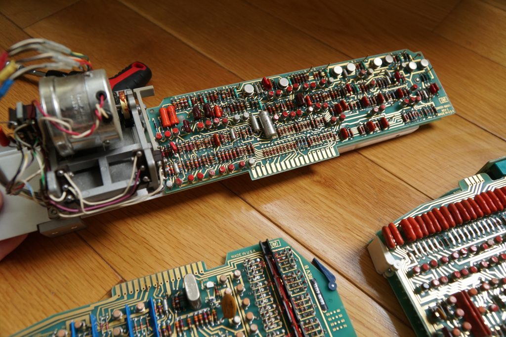
3-Channel Magnetic Card Reader